BeebControl>>Cyber 310>>Documents |
Here's a roundup of the few fragments of info I've acquired on the Cyber 310, starting with copies of a couple of vital pages from the manual, courtesy of the arm's designer
The two pages below were sent to me by David Sands. They were the only ones he could locate out of the originals after all these years. Nevertheless, they should provide enough clues for anyone wishing to write control software to drive a Cyber 310 via a BBC B, or most other micros for that matter.
Be aware, however, that the pin numbers shown in the manual's column for the BBC B do not represent cable connections at the robot-end - they simply indicate a standard flat IDC cable plugged into the userport. Use the separate pin diagram lower down if you need to make up a lead for an ex-Beeb arm.
STOP PRESS: I've now received a set of scans of the full manual, kindly supplied by Bryan Howe at the Cambridge Museum of Technology. So as soon as they've had a little further processing and conversion to a PDF document, I'll get them uploaded to their own 'Manual' page.
|
|
 |
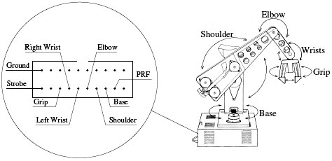 |
This diagram is borrowed from the Lithuanian site (see links page) and has been tested and found to work. The pin assignments are as viewed looking into the socket in the arm's base.
Note that the pin diagram on the French, Hector site is not correct for the Beeb, though I'm sure it will be correct for the Hector. A number of the lines are displaced by one pin from what's required for a BBC's user port cable. |
Misc notes while dismantling
- Transmission belts. Shoulder upper belt says "UNIROYAL PowerGrip 150XL025." (=75 teeth, ¼" (6.35mm) wide. Probably XL series = 150XL-025 .)
Shoulder lower belt says "UNIROYAL PowerGrip 80175 x ¼" AI7NI." (=175 teeth, 6.35mm wide. Probably MXL series = 1400MXL-025 .)
- Control wire. Wire is 1/32" diameter, multi-strand stainless steel. Nearest modern equivalent would be 0.81mm diameter, 7x7 strand, from Techni-cable, which I used successfully to repair my arm. A few of their Code 1 aluminium ferrules were also needed.
- Motor numbers. The motor-drive plugs on the PCB are numbered 1-6, from left to right on my board (the Lithuanian site seems to have them numbered right-to-left). A joint letter is marked next to each socket - B,S,E etc, but these can't always be seen unless the PCB is entirely out of the case, plus it isn't obvious which motor does what for some of the joints. FWIW, the motors match up with the following numbered plugs: base motor=1, shoulder motor (in column)=2, top motor on arm=3, bottom motor under the arm=6, left motor of lower pair=4, right motor of lower pair=5.
- Current drain. The motor driver circuits pass about 680mA through each of the six big 8 ohm limit resistors while the motors are stationary, meaning the resistors run very hot (180-200 degrees C). If any motor is stalled/jammed between rotor step positions then excessive current will pass through the relevant resistor and it will overheat until it smokes (and no doubt burn out fairly quickly if the arm is not shut down). Motor jam/seizure is most likely with the shoulder motor. The intermediate pulley rides in a very small steel/alloy bearing whose lube can dry up and lock the shaft/belt/motor system, resulting in an overheating resistor on the base board.
|
<< Cyber 310All content on this website is © Neil Fazakerley or its originators |
|