BeebControl>>Cyber 310>>Electrics |
Here's my design for a free-standing Cyber 310 control pendant - I've added more details plus a schematic if any other owners fancy making one.
As the Cyber arm generates its own stepper signals internally, it struck me that control via a pendant ought to be possible if a suitable chain of trigger and strobe pulses could be generated. The result is that I'm now controlling my Cyber 310 independently of any computer connection, making the arm much more portable and fun to use. |
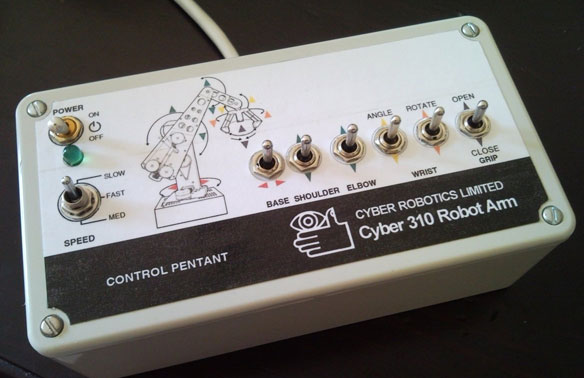 |
The neat control box shown here was built by Roger Hardie to this design but the very professional graphics are all Roger's own work. He's now enjoying watching his Cyber arm move again after 19 years of electronic immobility. (Unfortunately his first go at the electronics showed up an error with the clock timing components in my schematic. The circuit has now been corrected, so it should be plain sailing for future builders.) |
The control signals are generated by a 555 timer acting as a clock oscillator and a few logic chips that gate down the clock train to produce a suitable set of pulses for the various strobe and motor lines. I took the opportunity to include a 3-way step-speed switch as well. The ability to inch the various limbs into exact position using 'creep speed' should be very useful, especially for novice operators.
None of the passive components have very crucial values - near enough will do. You could also experiment with the values of the three caps around the speed switch to suit your own needs. |
 |
|
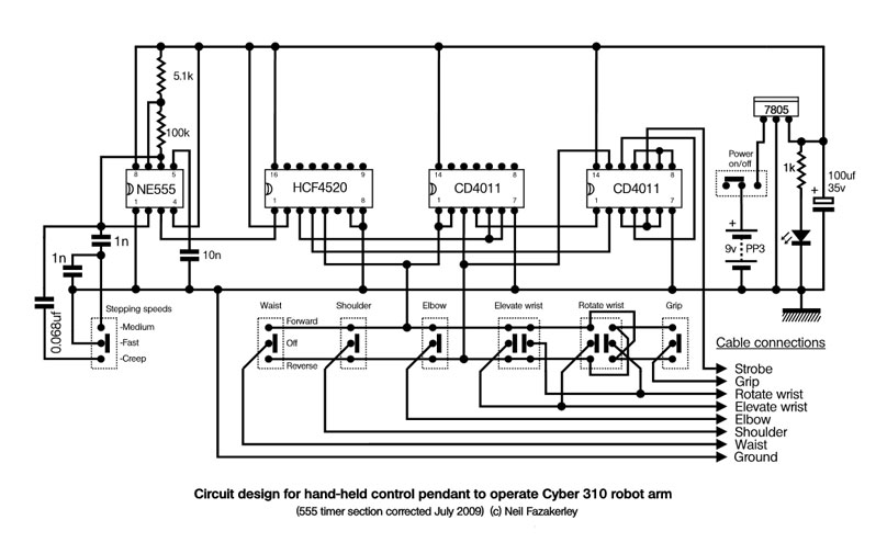
Here's the schematic (drawn using DrawPlus X2 on a PC if you're interested). I knocked my circuit up on prototyping board - which is like Veroboard but has rows of four-hole tracks rather than continuous strips. Vero would be fine but my scrap of proto-board needed using up so that's what I employed. In a similar vein, I used whatever chips I had lying around rather than choosing the ideal parts for the circuit and paying for a special order. Hence the use of rather old CD4011 CMOS NAND chips pulled from old circuit boards. Even the HCF4520 4-stage binary counter is probably obsolete by now. Still, they all seem to work well together, so 'if it ain't broke why spend money fixing it?' Apart from a 9v battery, the only items I needed to purchase were the six two-way momentary-contact switches (from Maplin) as I didn't have anything like them in the recycle box. |
|
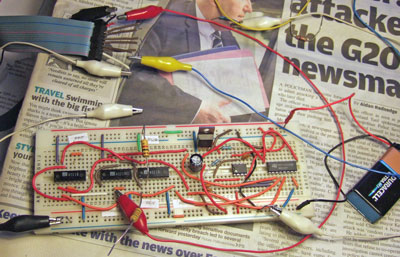
Incidentally, if you're familiar with the Cyber's control lines you may have spotted that there is no PRF control signal shown. When I was testing the breadboard prototype of the pendant (see right) I noticed that one of the croc leads had come adrift, yet the arm still responded as intended. That lead supplied the PRF signal. So I took the hint and left it out of the final design - saving use of a further CD4011 chip in the process. I'm assuming this is an artifact of CMOS chips driving TTL chips, but it would be interesting to modify an existing piece of Cyber control software and see if it too would function without the PRF line operating. |
 |
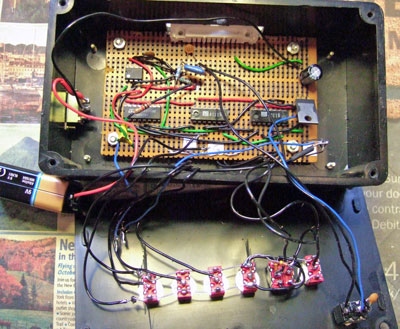
Here's the internals of the 'finished ' item - messy but effective. I didn't have two DPDT switches necessary for the wrist operation (the local Maplin only had one in stock) so I bodged the switching with a couple of diodes to achieve the same effect. Better to use two DPDT switches if possible though.
With hindsight it strikes me that as the HCF4520 contains a pair of binary counters in one package, I could have set them up to count positive clock edges on one counter and negative edges on the other. This would automatically have made a set of inverted signals available for gating and saved yet another CD4011 NAND chip. So in theory the board could be simplified further, to three chips and a voltage regulator. |
 |
<< Cyber 310All content on this website is © Neil Fazakerley or its originators |
|